I was shocked when I heard Gail Banks claim his aftermarket cold air intake (CAI) improved fuel economy (aka part throttle performance). I rushed out and bought his cold air intake for my Gen III Small Block Chevy (SBC) build, specifically a LQ9 6.0L. Most aftermarket parts are solely designed with one metric in mind, wide open throttle (WOT). Vehicles seldom operate at WOT. I rushed out and purchased a Bank’s CAI. Here’s what I learned…
Before I get too far down this rabbit hole. The quality of the Banks Cold Air Intake is second to none. There’s a couple minor nuances with fitment, mainly in the instructions. That aside, I’m seriously impressed with the attention to detail that went into making this intake. It’s clear Gail Banks and his team want to do good by their customers.
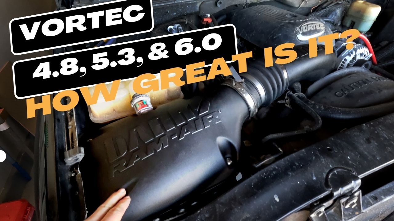
You can see an unboxing and install video I made below:
Today we are going to see if I cannot discern this CAI’s part throttle performance so let’s get started.
Measuring Intake performance
Fuel Consumption I’ve calculated my MPG since owning the truck and couldn’t see any noticeable difference in fuel consumption after installing the intake. Maybe if I did a circuit of 150 miles with one intake then repeated it with the other, had cruise set, and there was ZERO traffic. However, I’m not about to burn gas in that fashion. Simply logging MPG wasn’t enough to tell me what operating range the intake was best at. I’ve also made so many changes to the truck that it’s hard to see what all has influenced the fuel consumption.
Engine Flow Bench my engine controller, a Delphi P01, calculates airmass based directly off of mass air flow (MAF) and or indirectly with manifold absolute pressure (MAP). These measurements are run through a routine referred to as dynamic airflow to arrive at a accurate airmass measurement. Any errors in that airmass are detected as extra oxygen in the exhaust for which the controller then further refines the fuel delivery. My thoughts are to query the PCM for those measurements, log them, and get intake airflow for the CAI. More further on in this article…

To calibrate MAF or not to calibrate MAF
A mass airflow sensor (MAF) measures airmass given air movement across a sensor and through a known aperture size. Using the ideal gas law (sensor readings) and a known volume (aperture) it can measure airmass.
Hot Wire Principle The sensor is a heating element which varies in resistance as air flows over it. A given amount of airmass is required to cool the element down. The controller is able to observe the sensor element electrically as it’s temperature changes to arrive at intake airmass. The GEN III SBC also uses a reference cold wire sensor to measure ambient temperature providing an ambient reference.
There’s two styles of MAF sensors; bypass style and direct flow. The Gen III Small Block Chevy uses a direct flow style as on right hand side below. Note the bypass style does not include the intake aperture!

The direct flow MAF meters the entire intake column of air, not just a scoop of air from the column inside the air intake. The bypass MAF relies on the air intake being a specific size where it’s installed. If the intake diameter changes with a bypass style then the airmass changes so it needs recalibrated! Conversely, the aperture size never changes on a direct flow MAF so why calibrate?

Factory Gen III SBC 85mm MAF Curve
Common advice on the internet is to calibrate the factory GEN 3 SBC MAF sensor. There maybe some argument for velocity of airmass across the sensor element which could influence heat transfer (cooling). However, a change velocity would also mean a change in airmass which by definition is already influencing the sensor element. Long story short, I’m not 100% convinced velocity is independent of airmass.

Recalibrated MAF Curve on my modified Gen III SBC
I did go down the rabbit hole and calibrate my MAF sensor several times with different intakes. The curve clipped clipped (shown above). Calibrating a MAF sensor assumes you have “ideal” conditions and factory baseline engine. Those conditions are completely impossible to obtain without a flow bench and possibly more measurements only the manufacturer would have.
I ended up hiring a professional tuner whom used the factory MAF calibration. His calibration was able to hit airmass nearly DEAD on (LTFT within +/- 2%). All he had was a list of modifications I did to my truck In hindsight I prefer to leave the MAF curve alone!
Regardless, for sake of this experiment MAF calibration has to be held constant along with the engine tune. We’re going to vary only one thing, the air intake configuration.
Engine flow bench
We want to see improved VE given throttle position across engine operating speeds. In short, when I put on the Banks intake I’d expect to see more airmass in the cylinders than with the factory intake for part throttle (e.g. under 50%) if their claims are accurate.
Measurements
The idea is to log airmass / cylinder fill for given throttle position and engine speed (RPM). It maybe prudent to capture additional parameters which should correlate with cylinder airmass as calculated by the PCM:
- Cylinder Airmass
- MAF Frequency
- MAP
- Injector pulse width
Fuel maybe a bit tricky as the PCM also models transient fuel conditions, increasing fuel under dynamic throttle conditions. We will do our best to filter those out per below:
Dynamic Throttle: filter out data where the throttle increased over 5% in 500ms.
A air intake is limited by the ambient air conditions so we will want to look at intake air temperature. I’m also going to log vehicle speed to see if there’s an impact on ram air performance. Fuel trims and logging wideband maybe prudent as well. We can correct any error in the airmass calculation as performed by the engine. Of course we’ll need RPM, throttle position, and engine coolant temp (only log when warmed up).
- Intake Air Temperature
- Engine coolant temp
- Vehicle speed
- Engine Speed (RPM)
- Throttle Position
- Commanded AFR
- Fuel Trims and closed loop status
- Wideband Oxygen Meter
Measurement normalization:
The fuel trims in closed loop tell us the error in the air measurement during stoic (AFR of 14.7:1) operation. The factory tolerates an error in airmass up to +/- 25% and I’d say a good running vehicle is under +/- 5%. In any case, this will affect the resolution of our observations. I’d like to see under 1% error which can only be accounted for with a wideband sensor.
I further normalize the data via the ideal gas law and intake air temperature. This removes at least one more variable that could influence airmass available for intake to consume. Assuming ambient air pressure (same test track), and volume of intake (not big assumption there) are constant, I can then normalize IAT to standard temperature (273.15K).
AFR Correction: (Wideband Reading) / (Commanded AFR)
Standard Temperature: (Intake Air Temperature in K) / (Standard Temperature 273.15K)
Scaling the airmass accordingly (AFR Correction) * (Standard Temperature Adjustment) * Airmass
Datalogging
Most all of my archived data logs have the aforementioned measurements in them. The first order of business is to see if the normalized data per above is repeatable.
Repeatability:
The below measurements were all taken with the Banks CAI, same dynamic airflow (VE & MAF) calibration in PCM. First four data sets are airmass in relation to throttle position and vehicle speed.


This next four datasets are in RPM and throttle position in relation to airmass.


There is some variability in the data as to be expected.
NOTE: I’ve been unable to determine why HPT VCM scanner collects more data when I use a math parameter than when I log PID(s) directly. It’s one of those great mysteries their engineers and community has yet to answer. I assume it’s populating data based off the highest frequency sampling and not the other way around as it should be! There is no means in HPT Scanner to set the sample rate. I digress, this topic is for another day.
Contrasting data from intakes


Normalized data from Banks CAI for part throttle in 4th gear


Normalized data from Factory Intake for Part throttle in 4th gear
Ram Air Effect: the factory intake is designed to have some ram air effect. The fender has a scoop in it which mates with the factory airbox to ingest air from by the passenger side headlamp. These mate well. The Banks CAI continued in this tradition, however, it did not have a male connection, rather was a female to female connection. However, the banks has a large opening in front of the fender to consume air which the factory lacks.

Picture from inside Banks CAI showing fender mating surface for factory intake
It would be interesting to measure underhold temperature to intake air temperature to see which airbox ingests the coolest air as a result. Again I couldn’t find any data sets where the Banks CAI outperformed the factory airbox.
It appears the Banks CAI delivers less airmass throughout the part throttle range. I couldn’t find a single dataset in my logs that showed otherwise. Looking at the charts the Banks CAI seems to need up to 5% more throttle than factory intake to ingest the equivalent airmass.
Conclusion
This method of using my engine as a flow bench isn’t perfectly repeatable. It would take a great deal more data an analysis to say what measurement confidence is. I’d say we could make general conclusions though.
I did not test WOT performance this was intended to measure part throttle performance. There should be a point where the Banks CAI would ingest more air for a given throttle position and RPM. That point appears to be around 50% throttle if the data trends continue.
I’ve yet to see any meaningful difference in gas mileage with the Banks CAI so for all intensive purposes it’s good enough at part throttle, at most 5% less efficient at part throttle performance (under 50% throttle). Measurement variability might lower that figure a bit.
This would never stand up to a scientific peer review. I’d need to eliminate more variability in the study through isolation of more control variables and or collect MUCH more data at which point why not just find a flow bench. However, it did give a general idea of real world intake performance. While the Banks CAI is a high quality piece, unfortunately it’s not meaningfully better at part throttle performance.
Improving on part throttle performance is extremely hard. The factory has complete models and decades of experience doing exactly that. They don’t share that information publicly. Unless somebody designing the aftermarket part was a former factory engineer for the specific automaker (e.g. General Motors) on the specific part in question motor / air intake I’d be skeptical they were able to do anything other than improve WOT performance.
Manufacturers love to cut corners though. Banks does not, that’s abundantly clear. This is a quality piece and much better construction than factory.
Next Steps
I’d honestly, be inclined to put back on the factory intake. However, mine is pretty well shot so I’m okay leaving this Banks CAI on. I’d not buy it again though. My truck seldom goes over 50% throttle and mostly lives around 25% highway and even lower city. The factory intake performed better there.
I’d wanted to mix and match intake parts however, that’s off the table. The Banks CAI air box and intake plenum are different lengths than the factory design so you cannot interchange them. This would require cutting the baffles off a factory intake. Maybe a future test?
If you plan on improving part throttle performance it’s likely better to seek inspiration and parts from the auto manufacturers themselves.